Delineating a Rational Profession:
The Machine Drawings of Engineers in
Early Nineteenth-Century Britain
- Frances Robertson
_______________________________
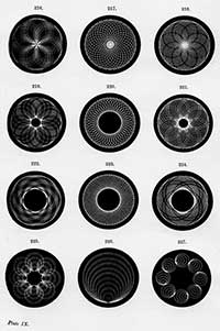
Fig. 4. Example of patterns generated
by the rose engine lathe, 1894 
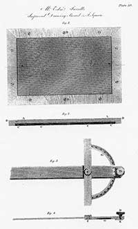
Fig. 5. “Mr. Edmund Turrell’s Improved
Drawing Board and T-square”, 1816
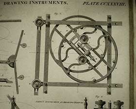
Fig. 6. “Elliptograph”, 1830
Other inventions though had a different function; they were not optical aids, but instead were literally drawing machines that automatically generated complex forms supplanting the skill of the human hand, for example with the invention of the rose engine in security printing for banknotes, or when James Watt, late in life, worked on a sculpting machine inspired by the sight of medal engraving' machines [12]. Many specialized instruments developed in association with this technical visual culture with artfully crafted portmanteau names such as elliptograph, curvagraph, or centrolinead displayed the mechanical arts in a reflexive manner, perversely turning the more normal progression of technical drawing as a proposal for a finished machine on its head. Instead machines made drawings.
This article will introduce a range of devices from apparently simple machines for ruling lines through to more complex offerings. While the names may be strange, the appearance of many of these instruments will be familiar to readers as images on the page, as typical examples of diagrams and illustrations from the era of useful knowledge' and the encyclopaedias. However, and to complicate the spirit of textimage, it is important to state that image-text analysis alone cannot fully provide a meaning for the machines or their images. Instead, it is necessary to examine the material circumstances of production by seeking out and handling surviving instruments in collections. Getting access to such archives is not easy, but the resulting encounters with the objects are irreplaceable. Handling these often obdurate objects forces new questions and approaches on the researcher, inviting new narratives about the interaction between procedures for making and using drawing equipment. Hands-on research showed that many devices were exceptionally troublesome to operate, and raised many other questions about the gap between the enthusiastic promotion of invention and their actual usefulness as drawing aids once realised. Nevertheless, this encounter also provided evidence to argue that these flawed machinesand the drawings they produceddid contribute just as much as large heroic projects did to the self-fashioning of engineers and engineering.
Ruling a straight line is such a basic operation it is almost invisible. But twentieth-century and contemporary perceptions of the straight lineseen as simple or totally boringare misleading. In the late eighteenth and early nineteenth century straight ruled lines were instead the focus for inventive attention. In print, straight lines were energized through the well-known ruling machine invented by the engraver Wilson Lowry around 1790. Engravers embraced Lowry’s machine, with its unvarying and mechanically spaced lines, that, according to the Transactions of the Society of Arts of 1826, was as useful as the steam engine is to the manufacturer.' In collaboration with the technical draughtsman John Farey, Lowry’s diamond etched lines, praised for their admirable degree of regularity and sweetness' crept across thousands of plates for encyclopaedias, self-help publications and mechanics’ magazines [13]. The extreme accuracy and neatness of Lowry’s drawing machine led to a kind of technological brinkmanship, evidenced by the note of desperation in engraver Edmund Turrell’s announcement to the Society of Arts of a modified drawing board with an especially smooth surface to cope with the frightening perfection of machine-ruled lines [14]. More complex forms, such as ellipses, offered an equally powerful lure to inventors [15]. While it was often claimed that drawing machines were simply the most efficient means of image production, the excessive and superhumanly regular forms they made went far beyond functionality.
Drawing machines and the apparent geometrical perfection of drawings made by these means raised all kinds of material and philosophical conundrums. In technical drawing on paper, a ruled line is a command to produce a straight edge or flat plane surface; in short it denotes something that has to be achievable in the real world. Much basic equipment of industrial production relied on reliable flat planes, although a flat surface was one of the hardest forms to produce [16]. In everyday engineering practice, and certainly up to the later part of the nineteenth century, straight edges were more often produced by empirical methods. In this artisanal approach, the method for making a flat plane or straight line is to shape by eye, checking with spirit levels and so on, and then (for flat planes) to test three planes against one another, slowly eliminating hollows or bumps with a file until the edge is as flat as possible. Craftsmen held on to their master' testing edges very carefully and avoided chipping or denting them. But this poses the logical problem of retrogression: where does your first straight edge come from? George Adams Jr., instrument maker and author of Geometrical and Graphical Essays, made a great fuss about the material difficulties of cutting a line onto the surface of his mathematical instruments in order to assert his personal craft expertise, writing at a time when it was agreed by everyone that straight lines and flat surfaces were a considerable manufacturing challenge. Rather than being easy, unskilled, or routine, Adams made it clear that it was particularly difficult to place and draw a straight line, finding it impossible to draw a knife a second time against the rule, and cut within the same line as before.' Adams used beam compasses to cut short intersecting arcs, raising up a metal bur, and thence by fingertip groping for the intersection (you may therefore feel what you cannot see
they will guide'), and thence, still working by feel, moving on to form further points [17] As a celebrated craftsman, Adams was reinforcing the trust of his customers in the accuracy of his work through this laborious description. The art of making reliable instruments with regular subdivisions of linear and angular measurements was known as graduation; we see from the article on this topic in the Edinburgh Encyclopaedia that such trusted and tested measuring instruments were important not just in their own right, as prized possessions, but also as the parents of many descendants, for they were then used to generate copies, and indeed, copies of copies.' [18]
However, as already noted, and despite the importance given to accurate lines and plane surfaces in industrial propaganda and in printed images, in many working situations in manufacturing, line marking continued in reality to be provisional and empirical. Straight lines were twanged in with chalk lines or plumb lines, while curves, so long as they passed through a few crucial calculated points, were laid in by eye or by bending elastic curves of whalebone, steel or wood. In drawing offices, only a few rulers were carefully and exquisitely made. The majority, as used by tradesmen or lowly draughtsmen in the Board of Ordnance (the state military cartographers), were simple wooden rules with unprotected edges [19]. The marks these laid down were accepted as provisional and merely conventional, their exactitude supplemented with written dimensions, but nevertheless most suitable for purpose. These circumstances only reinforce our initial question; why put so much effort into creating machines that drew to an unnecessarily ideal standard?
[12] Rose engines used the complexity of interchangeable gears harnessed to a rotating lathe action to generate the spirograph-like ‘rose’ patterns seen in Figures 1 and 4. For rose engines, see D.M Henshaw, ‘Donkin’s Pantagraph Engraving Machine with Rose Engine,’ Transactions of the Newcomen Society Volume XV, 1934-5, pp. 77-84; for medal engraving, please note this term is confusing because it is actually a method of transcribing a low-relief image such as a sculpture or medal onto a two-dimensional printed surface. The process was also known as anaglyptography. A ruling machine with two connected needle-points was used in the process; one needle traced the surface in relief, the other needle inscribed a recording surface; see A. McConnell, R.B. Bate of the Poultry, 1782-1847: The Life and Times of a Scientific Instrument Maker, London: Scientific Instrument Society Monograph, 1993, pp. 29-31.
[13] ‘Memoir of Wilson Lowry,’ Imperial Magazine Vol. VII February 1825, pp. 113-128; T.H. Fielding, The Art of Engraving, London: Ackermann, 1841; B. Hunnisett, A Dictionary of British Steel Engravers, Leigh-on-Sea: F. Lewis, 1980.
[14] Society of Arts Transactions 1816: 139-40.
[15] At least three ellipse-drawing devices jostled politely for the attention of the Society of Arts before 1820: Cubitt’s ellipsifex (Society of Arts Transactions 1816, pp. 131-7); Joseph Clement’s instrument for drawing ellipses, which was awarded a Gold Medal (Society of Arts Transactions 1818, pp. 133-77); and John Farey’s elliptograph, Society of Arts Transactions 1813, pp. 117-130).
[16] From George Adams Jr. in the 1790s, to A.B. Kempe in the 1870s, to Bryant and Sangwin in 2008, engineers, mathematicians and inventors have reiterated the fact that making a straight line (in chalk, metal, wood) is difficult, challenging, nay physically impossible. In the early nineteenth century, flat planes and straight edges were used for steam engine valves, lathe beds or printing press tables. The effort to master techniques for making plane surfaces became one of the standard tropes of industrial hagiography. So the first systematic user of the accurate standard plane for testing surfaces, Henry Maudslay, was cited over and over again in different industrial biographies, whilst inventors and owners of planing machines, such as Richard Roberts or Joseph Clement, could earn a substantial fortune from hiring out their magic by the hour. See George Adams, Jr. [1791], Geometrical and Graphical Essays, Fourth edition, corrected and enlarged by William Jones London: W.& S. Jones, 1813; A.B. Kempe, How to Draw a Straight Line; A Lecture on Linkages, London: Macmillan and Co., 1877; J. Bryant and C. Sangwin, How Round Is Your Circle?, Princeton: Princeton University Press, 2008; J. Cantrell and G. Cookson, eds, Henry Maudslay & The Pioneers of the Machine Age, Stroud, Gloucestershire: Tempus Publishing, 2002, pp. 28; 94; 111.
[17] Adams, 1813, pp. 112-13.
[18] ‘Graduation,’ Edinburgh Encyclopaedia, Volume 10, 1830, pp. 348-384.
[19] J.R. Millburn, ‘The Office of Ordnance and the Instrument Making Trade in the Mid-Eighteenth Century,’ Annals of Science 45, 1988, pp. 221-293; J. Rabone, Jr. [1866], ‘Measuring Rules’ in D. J. Hallam, The First 200 years—A Short History of Rabone Chesterman Limited, Birmingham: Rabone Chesterman, 1984, pp. 131-4; I. Watts, W.J.M. Rankine, F. K. Barnes, and J. R. Napier, Shipbuilding, Theoretical and Practical, London and Glasgow: William Mackenzie, 1866.


